Mechanical anisotropy: sources and implications
The mechanical behaviour of several rocks, such as schists, sandstones, shales and basalts, is characterized by strong stiffness and strength anisotropy . This anisotropy may arise at different spatial scales within the rock:
- mineral scale: laminated material micro-structure;
- centimetre scale: schistosity, foliation, and bedding planes;
- rock mass scale: presence of preferably oriented physical discontinuities (e.g., joints, tectonic structures).
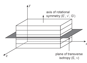
Most anisotropic rocks are best described as transversely isotropic bodies. That is, the deformability of these materials show isotropic properties within a plane that is normal to an axis of rotational symmetry.
Elastic constants associated with a transversely isotropic solid.
From a practical point of view, the mechanical anisotropy directly affects the stability of underground excavations and observed failure behaviour. In particular, the reduced strength properties of the interfaces between layers may result in enhanced instabilities with failure patterns far more extensive than those observed under isotropic material conditions.
Numerical models
Numerical modelling can be used to analyse the stability of structures in layered rock formations. The simulation approaches are generally classified according to the type of material representation, as
- Equivalent continuum methods: the presence of layers is smeared to produce a fictitious continuous material that exhibits mechanical characteristics that are similar to the original discontinuous medium. Examples: ubiquitous joint models, Cosserat-theory models, statistical damage models.
- Discrete element methods (DEMs): layers or joints are explicitly included into the numerical model, which represents the medium as an assembly of blocks or particles with interaction laws governing the emergent behaviour of the rock. Examples: Discontinuous Deformation Analysis (DDA) method, bonded-particle models, Distinct Element codes.
FDEM
A third category is represented by the hybrid finite-discrete element method (FDEM). With this approach, the elastic deformation of the material is described using continuum mechanics theory while DEM algorithms and non-linear fracture mechanics principles are employed to capture material failure. With Geomechanica’s FDEM code, the anisotropy of stiffness is captured at the triangular element level using a stress-strain constitutive law for linearly elastic, transversely isotropic solids. On the other hand, the anisotropy of strength can be simulated by
- the “discrete” approach: a distribution of finite-sized, cohesion-less fractures aligned with the plane of isotropy is introduced into the model:
- the “smeared” approach: the cohesive strength parameters of the fracture model are varied as function of the relative orientation between the element bonds and the layering orientation:
The discrete approach The discrete approach The discrete approach The discrete approach The discrete approach
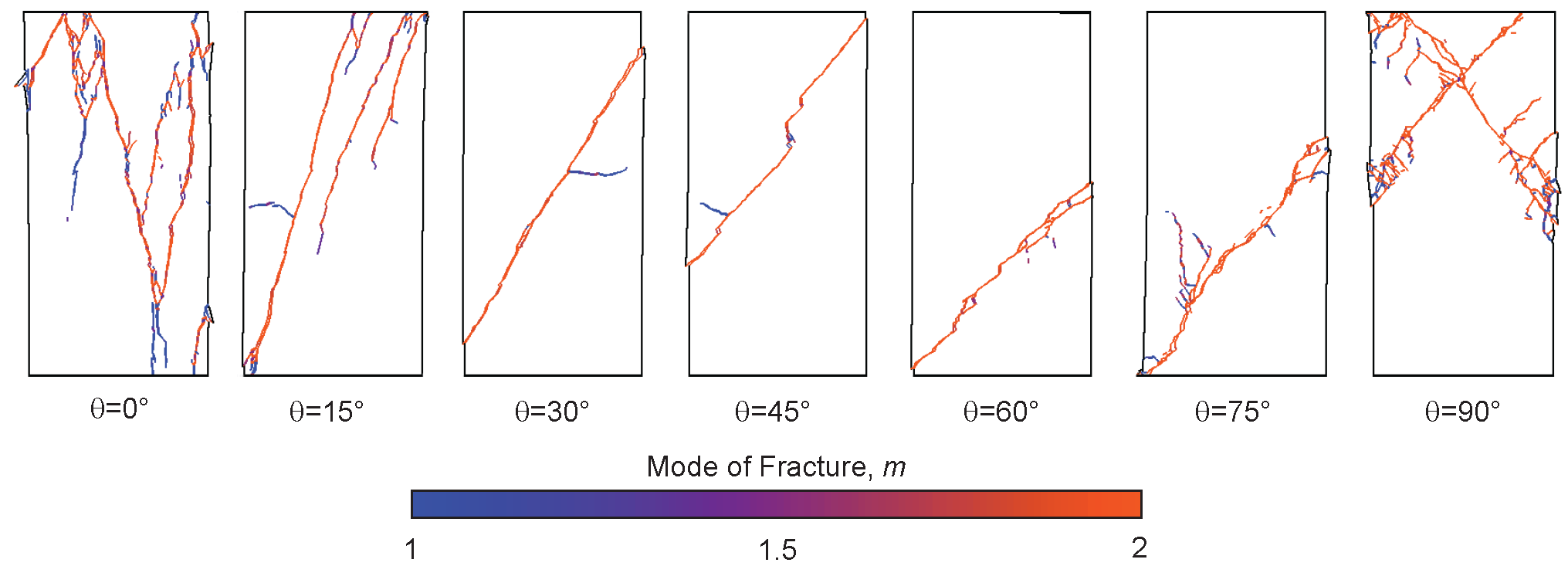
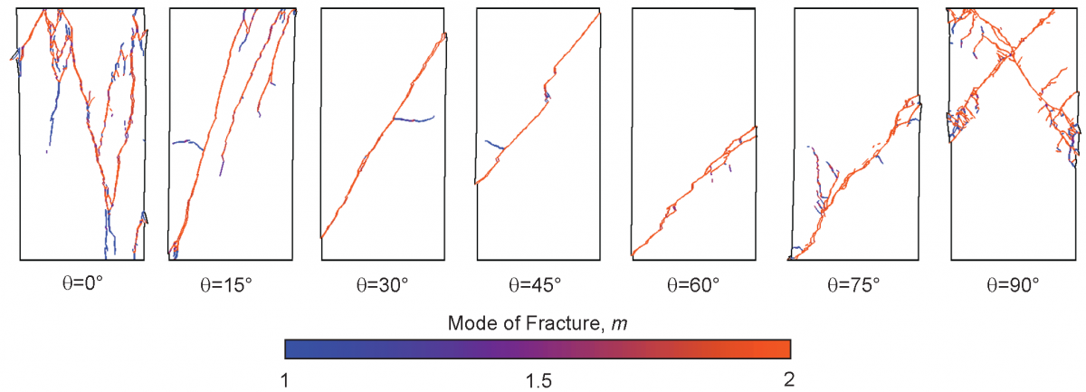
Fracture pattern and mode of fracture as function of bedding orientation
In the next post, we will discuss the applicability of these two techniques to the simulation of damage development around deep excavations in shales.


