We are excited to announce that we have implemented a mechanically-based model of the rock-reinforcement interaction process. The methodology represents an adaptation of the reinforcement elements first developed for FDEM analysis of reinforced concrete (Zivaljic et al. 2013) and modified to make them suitable for modelling rock masses. From a numerical viewpoint, the reinforcement model consists of of two additional entities that are super-imposed to the original triangular mesh: (i) a 1D element inside the triangles, and (ii) and a 1D joint element across the crack elements. The constitutive model of these new elements is, at present, limited to linear elastic.
Representation of a reinforced rock in FEMDEM. Triangular elements are shrunk for illustration purposes.
To illustrate the effectiveness of the newly-implemented approach, the excavation of a 3.0 m diameter tunnel in a weak rock mass was simulated. The rock mass was assumed isotropic and homogeneous and subjected to a maximum and minimum in-situ principal stress oriented in the horizontal and vertical direction, respectively: σ1=σh=25.5 MPa and σ3=σv=19.6 MPa. In a first simulation run, the tunnel was left uncased and no reinforcement was installed. The failure sequence of the tunnel with the associated contour of total displacement (see animation below) shows the collapse of the opening with the formation of a vertically-elongated fractured zone extending deep into the rock mass.
Simulation of fracturing around an uncased tunnel without reinforcement.
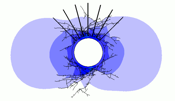
In a second run, the rock mass was reinforced with a pattern of 12 equally-spaced, 3 m long bolts installed in a radial pattern around the tunnel. As highlighted in the animation below, the passive reinforcement has little influence on the amount of fracture nucleation. However, as the strength of the bolt is mobilized, a retaining effect tends to develop, resulting in a substantial reduction of the large-displacement zone observed in the unreinforced model. In this case, the collapse of the tunnel is prevented and only a few small blocks appear to fall from the tunnel walls.
Simulation of fracturing around an uncased tunnel in a reinforced rock mass.
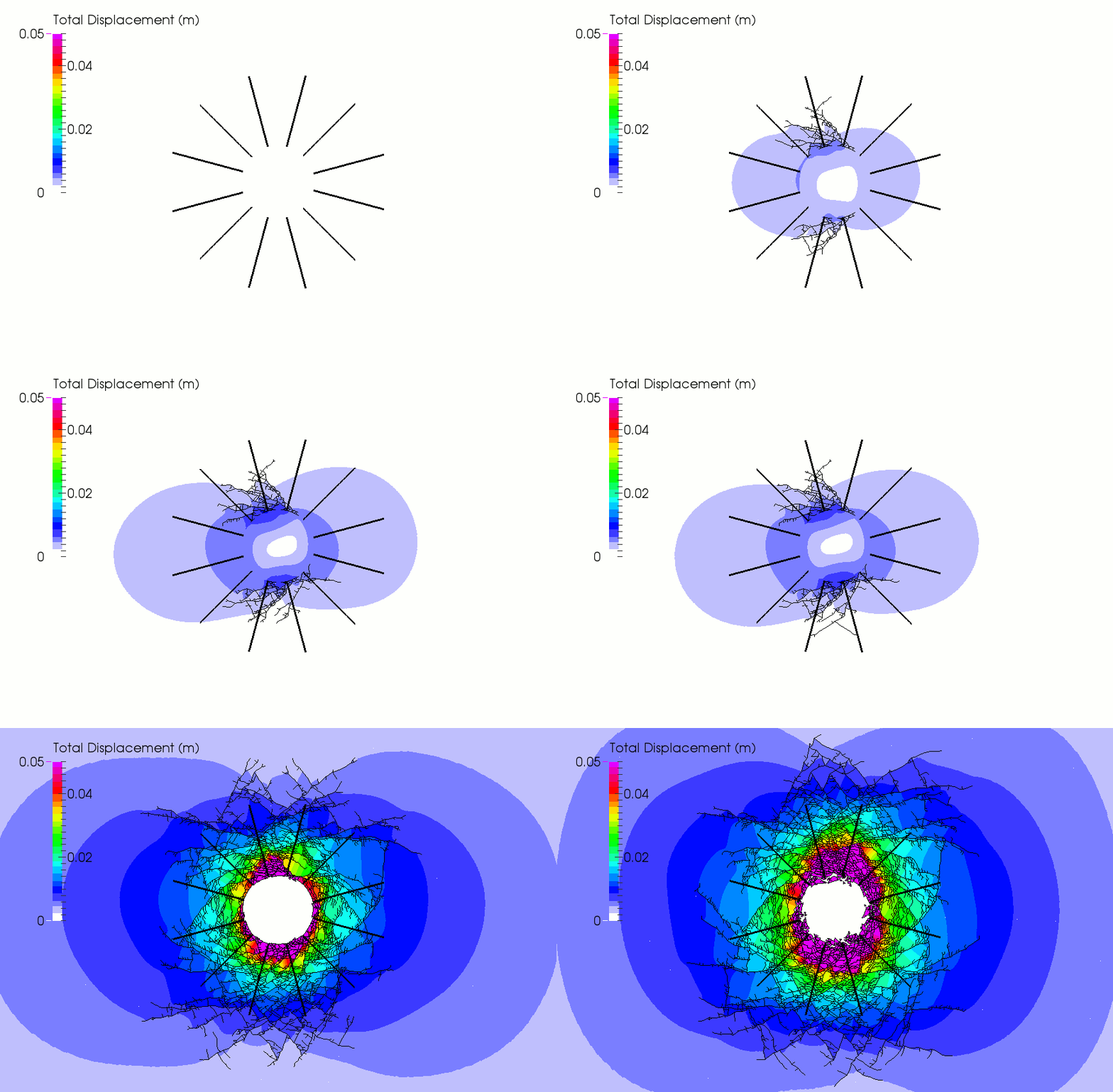
Finally, the effect of varying the number of bolts was investigated and the effect depicted in the figure below. As expected, the rock mass displacements are reduced as more reinforcement elements are incorporated into the model. For comparison, an early installation of a shotcrete liner (animation below) shows an even greater stabilizing effect with a substantial reduction of the number of fractures.
Comparison of fracture pattern and deformation field for different reinforcement scenarios.
Simulation of fracturing around a lined tunnel with bolt-reinforced roof.
Research and development is currently ongoing aimed at improving the reinforcement model formulation adopted for these conceptual simulations. Specifically, more complex constitutive relationships will be introduced to account for a number of factors such as the slip at the bolt-grout interface, the plastic behaviour of the bolts, and pre-tensioning effects.
Please note that this feature was experimental and is not currently available in Irazu simulation software.
References:
- Zivaljic N., Smoljanovic H., Nikolic Z., 2013. A combined finite-discrete element model for RC structures under dynamic loading. Engineering Computations, 30(7), 982-1010


