We are excited to announce that we have been working on the introduction of hydro-mechanical (H-M) coupling in our Irazu FDEM software. The introduction of H-M coupling arguably makes the Irazu software one of the most sophisticated simulation software currently available for geomechanical applications as a multitude of multi-physics processes can be taken into account, including:
- Rock elasticity, including isotropic and transversely isotropic material models
- Physics of discontinuous and heterogeneous systems, including the interaction between newly-created and existing discontinuities
- Brittle fracture processes (e.g., Mode I, Mode II, mixed-Mode fracturing)
- Coupled flow through porous media and effective stresses
- Fluid-driven fracture nucleation and growth (both toughness-dominated and viscous-dominated regimes)
- Emergent rock mass seismicity
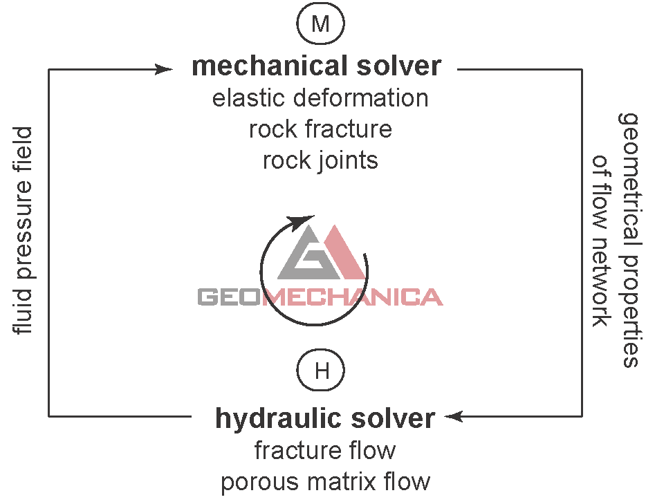
The H-M coupling is based on a two-way explicit coupling approach obtained by alternating between the mechanical and hydraulic solvers while marching forward in time. The approach is fully-coupled in the sense that:
- the mechanical calculations are affected by the presence of a fluid pressure acting inside the rock, thus resulting in the natural development of effective stresses within the model; and
- the flow calculations are affected by the mechanical deformation of the rock through variations, for example, of hydraulic fracture aperture and flow network geometry.
Two-way hydraulic-mechanical coupling implemented in Irazu.
In the fluid flow algorithm, a flow channel is assumed to exists at the interface between the triangular finite elements. The flow through each channel is idealized as a laminar viscous flow between two parallel plates using a cubic law approximation. The flow solver can capture the transient flow of a compressible fluid through newly-created fractures, existing rock mass discontinuities, and intact porous matrix.
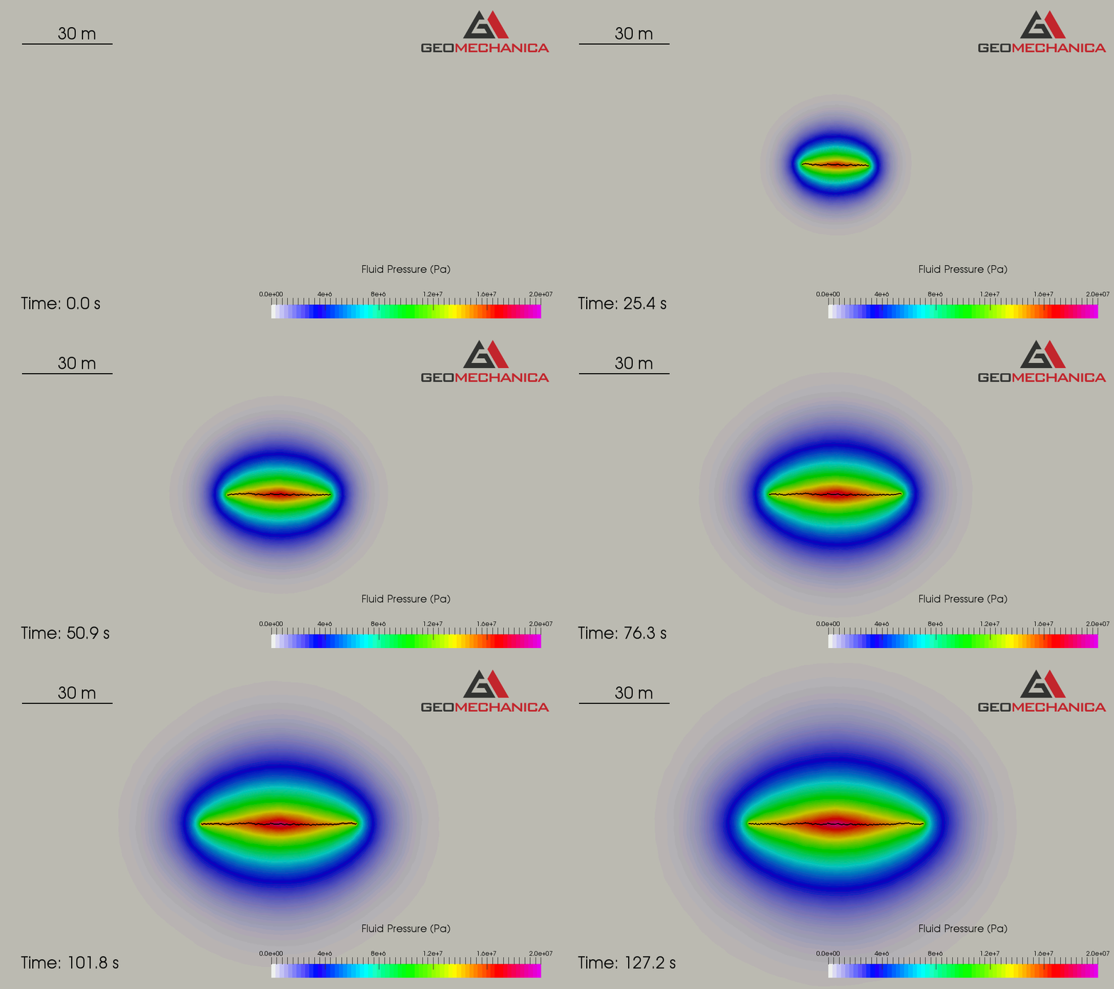
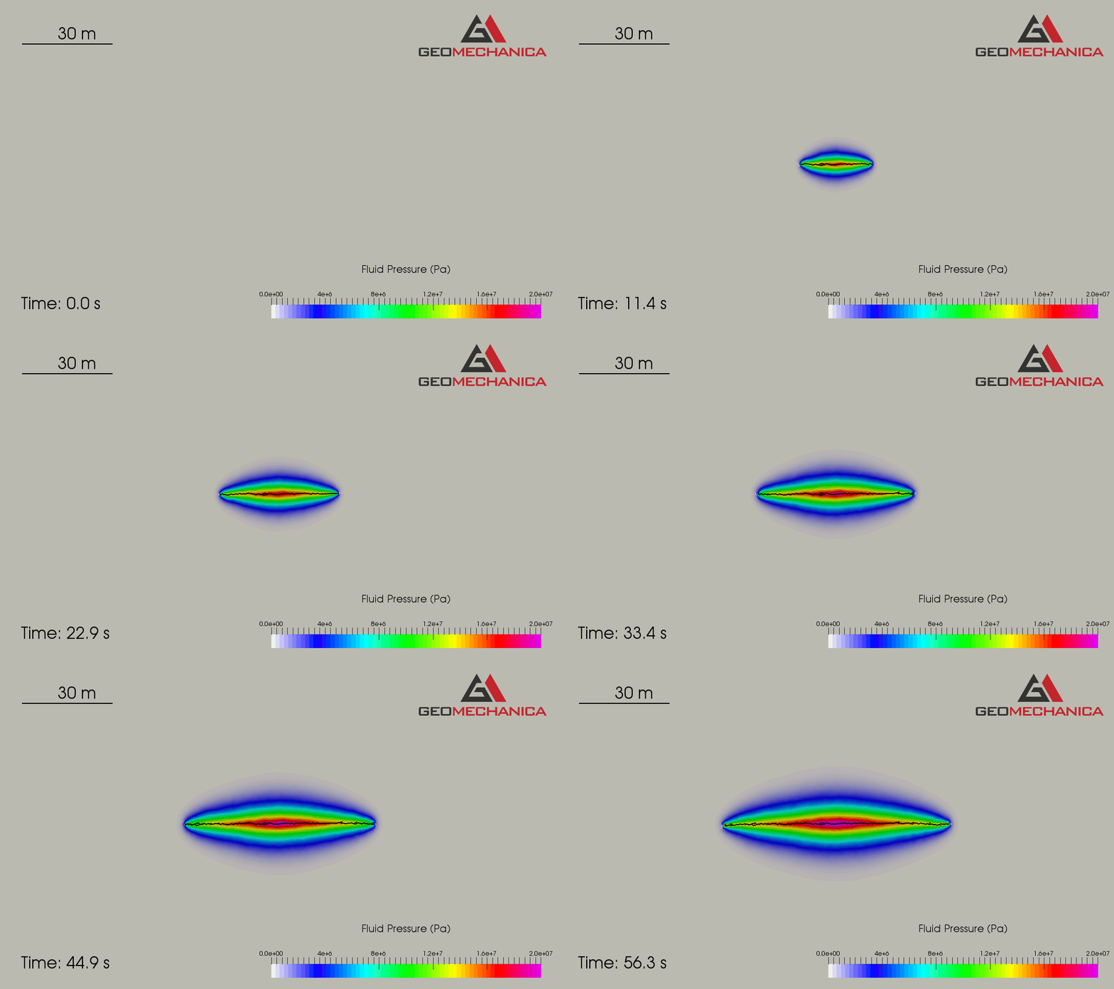
To exemplify the full H-M coupling, we consider the injection of water through a deep well in an initially dry, permeable rock mass. The in-situ stress field is characterized by a maximum and minimum in-situ principal stresses oriented in the horizontal and vertical direction, respectively: σ1=σh=20 MPa and σ3=σv=15 MPa. In a first simulation case, the rock mass is assumed to be homogeneous and isotropic with stiffness and strength property values typical of a brittle rock. The animations below show that the pressurization of the well causes the nucleation of a bi-wing tensile fracture parallel to the direction of σ1. The simulation results highlight the effect of the rock mass permeability k on the hydraulic fracture propagation process. As expected, a higher k value leads to a higher leak-off of fluid from the growing fracture, thus resulting in a slower fracture propagation speed and larger area of influence around the fracture.
Example of fluid-driven fracturing in a homogeneous and isotropic rock mass with permeability k = 4.5e-12 m2.
Example of fluid-driven fracturing in a homogeneous and isotropic rock mass with permeability k = 5.6e-13 m2.
In a second simulation case, the presence of a 20-m-long cohesive-type discontinuity (fault) is incorporated into the model with higher permeability (k = 4.5e-12 m2). The strength properties of the discontinuity are lower than those of the rock mass. As highlighted in the animation below, the seepage flow around the hydraulic fracture causes a progressive decrease of the normal effective stress acting along the fault plane, thus gradually reducing the mobilized frictional resistance. After about 76 seconds of injection, the fluid pressure induces fault slip (reverse faulting).
Example of fluid-pressure-induced fault slip (rock mass permeability k = 4.5e-12 m2).


